Category Archives: Raspberry Pi

Repurposing an old LCD TV into an interactive wall calendar

Now that I’ve upgraded the living room TV, I’ve moved my old 42” Plasma into our bedroom and I’m now left with a spare 22′ LCD TV.

Until now we had an old school paper wall calendar, mainly for birthdays and anniversaries, but let’s be honest we don’t look at it that often as it’s pretty much static (albeit with the monthly page flip)

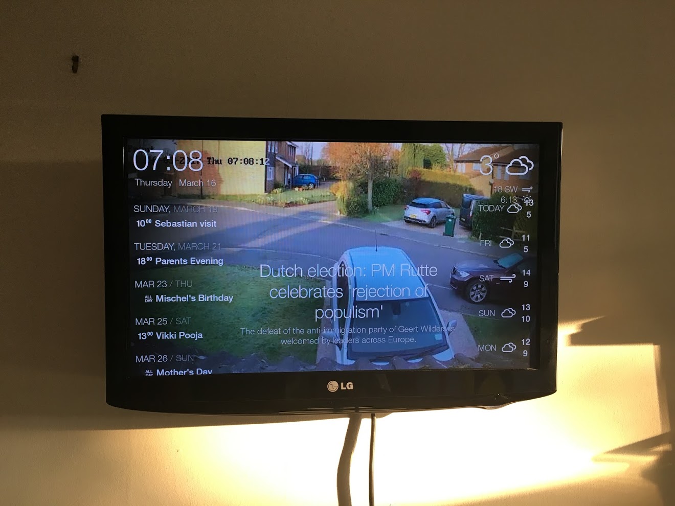
I’ve stumbled upon DAKBoard and decided to repurpose my old tv into an interactive wall Calendar.

It’s free to sign up and create your own dashboard. I set up a family calendar in Google, set my location for the weather, and changed the picture setting to pull the live feed from my CCTV.

First I bought a Raspberry Pi Zero W as the “brain” of the new calendar. It would really only be opening the DAKBoard site and that’s pretty much all. No need for a big Raspberry Pi.

Then I installed Raspbian Jessie on it, mounted it so I could edit the WiFi settings thanks to David Maitland’s post. (I have no micro USB to USB adapter so no way of interacting with the Raspberry Pi other than via WiFi, which needs setting up manually).

Once connected to WiFi, I SSH’ed on it to setup the usual VPN (I use TightVNC, not the built in VNC server) and Samba.

Now it’s time to set up DAKBoard to open automatically at startup:

  1. Edit /home/pi/.config/lxsession/LXDE-pi/autostart and add this line. (replace ########### with the key from DAKBoard under Account):
    @chromium-browser --disable-session-crashed-bubble --disable-infobars --incognito --kiosk http://dakboard.com/?p=###########


  2. install unclutter to hide the mouse:
    sudo apt-get install unclutter


  3. Disable screen blanking so the TV always shows the dashboard:
    sudo nano /etc/lightdm/lightdm.conf

    insert the below line in the [SeatDefault] block:

    xserver-command=X -s 0 dpms


  4. Disable the screensaver
  5. I then use DomotiGa and one of my LightWaveRF sockets to switch the TV on and off based on motion detection on my PIR
DAKBoard

DAKBoard

In the future I might look into dismantling the TV to get it to fit into a custom frame as per this instructable

[17th March 2017]

If you also plan on using VNC, there’s a chance that DAKBoard launched on the VNC display and not the HDMI display. If that’s the case, stop VNC from starting automatically. With my setup I set:

sudo systemctl disable [email protected]

(see this post for more info on how to setup TightVNC)

Then I simply added a line in /home/pi/.config/lxsession/LXDE-pi/autostart :

@nohup vncserver :1


LCD 3D Printed Custom Case

I’ve had my LCD Display screwed against a badly made piece of wood just so I could attach it to the wall.

After looking for a case for the display, I stumbled upon Thingiverse where “mmontee” had already done all the hard work. I headed over to 3DHubs and found a printer who did the job for me quickly and at a reasonable price.

I opted for a white case as I thought the display would stand out even more.

The printed case looks like this:

LCD Case Back Inside

LCD Case Back Inside

LCD Case Back Outside

LCD Case Back Outside

LCD Case Front Inside

LCD Case Front Inside

LCD Case Assembled

LCD Case Assembled

Case with LCD Fitted

Case with LCD Fitted


BME280 Weather Sensor

I had been eyeing a few temperature sensors on Adafruit for a while: I wanted to add a couple of sensors to get temperature and humidity. One sensor in particular would give me data that I don’t have so far: barometric pressure. This sensor is the BME280

Adafruit BME280

Adafruit BME280

I didn’t want to buy straight off Adafruit as the shipping costs were more expensive than the sensor itself (since they ship from the USA). I however found a retailer in the UK: Proto-Pic

It was pretty straight forward to add the sensor to the Raspberry Pi: 4 wires to solder on the sensor, and to the I2C / Power on the Pi.

Once connected, a quick check to confirm the I2C address of the sensor:

pi@raspberrypi $ sudo i2cdetect -y 0
0 1 2 3 4 5 6 7 8 9 a b c d e f
00: -- -- -- -- -- -- -- -- -- -- -- -- -- 
10: -- -- -- -- -- -- -- -- -- -- -- -- -- -- -- -- 
20: -- -- -- -- -- -- -- -- -- -- -- -- -- -- -- -- 
30: -- -- -- -- -- -- -- -- -- -- -- -- -- -- -- -- 
40: -- -- -- -- -- -- -- -- -- -- -- -- -- -- -- -- 
50: -- -- -- -- -- -- -- -- -- -- -- -- -- -- -- -- 
60: -- -- -- -- -- -- -- -- -- -- -- -- -- -- -- -- 
70: -- -- -- -- -- -- -- 77

(Note you may need to replace the 0 with a 1 depending on the version of your Raspberry Pi)

By default, the i2c address is 0x77. If you add a jumper from SDO to GND, the address will change to 0x76. See Adafruit’s tutorial for more info.

From there on, I just skipped to the last page to get the python script. Downloaded, installed, and it’s working.

One point to note is that I actually ordered a BMP280 from Proto-Pic which does not provide humidity data:

pi@raspberrypi $ sudo python Adafruit_BME280_Example.py 
Timestamp = 124328.000
Temp = 24.3 deg C
Pressure = 1000 hPa
Humidity = 0 %


Using 2 PIR sensors on 1 GPIO Port

I have an issue in my kitchen where the PIR, although optimally placed, is still too far to detect the small movements we make when we eat at the table.

I wanted to add another PIR close to the table, but I didn’t want to use another GPIO port on the Raspberry Pi when all I needed was another sensor for the same overall status: movement in the kitchen or not, (regardless of which sensor picks it up).

So what I’m after is a logical OR gate: if PIR1 OR PIR2 is on, then the status is on, otherwise it’s off.

The answer is actually quite simple and only requires 3 components: 2 diodes and a resistor:

OR Diode Logic Gate

OR Diode Logic Gate

  • Connect [3] to the output of PIR1
  • Connect [4] to the output of PIR2
  • Connect [1] to the GPIO port on the Raspberry Pi

Et voila! 2 PIRs for improved motion coverage, but only 1 GPIO port used 😎


Humble Pi

I’ve been using a breadboard on top of my Raspberry Pi for a while now to connect components to the GPIO ports.

Pros:

  • Easy to test
  • Easy to make changes
  • Easy to reset individual components by removing their power supply
  • Not “set in stone”

Cons:

  • Fragile, jump cables can be easily disconnected
  • Not secure, cables, resistors and other components could be pushed against each other, creating short-circuits
  • Not aesthetically pleasing

The not aesthetically pleasing is probably best described by a picture:

Breadboard On Pi

Breadboard On Pi

I’ve decided it was time for me to become confident and stop the try and error approach. I’ve not changed the setup / layout in months now and use many components integrally as part of my home automation system like PIRs to control lighing. I’ve therefore purchased a Humble Pi from HobbyTronics to make everything a little bit less like work in progress in the lab:

Humble Pi Stage 1

Humble Pi Stage 1

the board came as a kit with all parts separated. I’ve already soldered the header socket and made minor, direct connections to some of the GPIO pins in preparation to the upcoming components:

Humble Pi Stage 2

Humble Pi Stage 2

And I’ve checked that it fits in the case. Actually looks pretty cool. Will have to decide how to get the wires to get through though

Humble Pi Stage 3

Humble Pi Stage 3

The other thing I’d like to do is to ensure I can keep the drop cover on to protect the Pi against accidental damages, but I still need all my sensor wires to get in. I’ve therefore sawn a slot off to allow for this:

Pi Case with additional slot

Pi Case with additional slot

Now I need to complete the soldering of all the components. I’ll post a picture when I’ve finished.

[3rd December 2014]

I’ve finally done it! No more messy breadboard, it’s all nice and tidy now 🙂

Humble Pi Completed

Humble Pi Completed


DomotiGa, SmartVISU & Raspberry Pi

I’ve done it ! Finally completed installation of DomotiGa and SmartVISU. Below are only screenshots of draft setup as I still have to add some sensors and improvements, but it’s a start.

DomotiGa

DomotiGa


As DomogiGa is not directly compatible with GPIO ports (and since it’s installed on a different server anyway), my DomotiGa sensors are actually Shell devices which point to Python scripts (which connect to a MySQL DB and return the value of each sensor). Each Shell device gets automatically updated every 300 sec in DomotiGa by default, so to ensure I get live data I have added JSON-RPC calls in my GPIO script:

My GPIO Python script calls a bash file that contains the JSON-RPC Call:

curl -sS -X POST -H "Content-Type: application/json" -H "Accept: application/json" -d '{"jsonrpc": "2.0", "method": "device.set", "params": {"device_id": 2, "value": "On"}, "id": 2}' [server_ip_address]:9090

(I always send the value “On” but since DomotiGa will run the Python script following the JSON-RPC call it doesn’t matter)

My Python script for DomotiGa Shell Device:

import MySQLdb as mdb

con = mdb.connect(sqlhost, sqlusername, sqlpassword, sqltable)
cur = con.cursor()
cur.execute("SELECT pinStatus FROM pinStatus WHERE pinNumber=22")
row = cur.fetchone()
if(row[0] == '1'):
print "On"
else:
print "Off"
con.close()

My SmartVISU page contains this type of script for each device:

{{ basic.symbol('PIR1_Off', 'PIR1_switch', 'PIR 1', icon1~'message_presence.png', 0) }}{{ basic.symbol('PIR1_On', 'PIR1_switch', 'PIR 1', icon1~'message_presence_active.png', 1) }}


RPi HTML5 Control Panel

I wanted to improve the way I display the status of my sensors and decided to venture away from a simple table with icons and check out HTML5 for a more graphical display.

There are still a few tweaks to added:

  • Refreshing only the HTML canvas (drawings) rather than the whole page every 5 sec
  • At the moment only the CCTV and Temperature are, I need to add buzzer control

But for a proof of concept, I’m rather happy with the outcome.

RPi HTML5 Control Panel

RPi HTML5 Control Panel


Glade PIR – Update

I decided the “hacked” Glade PIR didn’t cut it.

  1. It responds to light conditions so a sudden change in lighting (sun & clouds) could trigger it
  2. It’s completely useless at night since without light it cannot detect movement linked to change in light conditions

I therefore decided to buy another “real” PIR from Tandy. I however had a hole on the wall and all the wiring ready so I simply cut a whole in the Glade housing to fit the PIR.

PIR Motion Sensor Module

PIR Motion Sensor Module

Glade PIR V2

Glade PIR V2


LCD Brightness

The LCD display is stable enough for now that I don’t need to keep an eye on it (using a separate program to update it sorts any glitches out by re-initialising it).

However the brightness is just not right. The LCD was intended to be used with an Arduino board so expects +5V VDD, however it only receives a +3.3V VDD from the RPi.
Powering the LCD with +5V but using the +3.3V on I2C bus was not working.

I’ve therefore purchased a Bi-directional Logic Level Converter (HERE), hoping to power the LCD with +5V and use the same voltage on the I2C bus at least at the LCD side:


4-channel Bi-directional Logic Level Converter

4-channel Bi-directional Logic Level Converter


I should hopefully set this up shortly and will update my findings here.


[Update – 30th Dec 2013]

The Logic Level Converter doesn’t do the trick. The LCD does not get recognised by the Pi. I’ve even tried to power it via a diode to drop the power support from 4.6V (read from a multimeter) down to 3.9V (0.7V loss via the diode), but the Pi still does not recognise it. I’m starting to think this is a poor LCD, but it can still be read when powered by +3.3V, even though it’s a bit dimmed.


[Update – 3rd Oct 2016]

I know I had many issues due to the breadboard as the LCD would even dim for half a second if a loud sharp noise was made close by. Since I have a Humble Pi, everything is a lot more stable, so I thought of revisiting the Logic Level Converter avenue, and it’s all up and running smoothly now 🙂

Oh and I’ve also got a custom case 3D printed, see this post for more info…

LCD with Logic Level Converter

LCD with Logic Level Converter


LCD Display

Until now the only way to check the status of some basic sensors (mainly the temperature) was to open the web interface I created.

I wanted an easier and quicker way to check the temperature and humidity. I therefore decided to get a small LCD screen to display that basic info.

I ended up buying a SainSmart® IIC/I2C/TWI Serial 2004 20×4 LCD Module from Amazon.

2013-07-26 07.18.24Since I wanted to display data from different script sources (main GPIO controller script, Temperature and humidity script) I soon realised I had to use a separate script to handle the LCD as opposed to a simple call to display data: 2 simultaneous calls (or in quick succession) would scramble the I2C port and the LCD would either not display anything or display garbage.

I therefore use a MySQL database to hold the messages, which can be updated by any of my scripts, and a separate LCD.py handler that loops and updates the LCD

Note: the LCD’s address is 0x3F. You can confirm it’s correctly detected by running:

i2cdetect -y 0

or

i2cdetect -y 1

(depending on the version of your Raspberry Pi).

The LCD needs to be powered by +5V, but then it does not get detected:

pi@raspberrypi $ sudo i2cdetect -y 0
0 1 2 3 4 5 6 7 8 9 a b c d e f
00: -- -- -- -- -- -- -- -- -- -- -- -- -- 
10: -- -- -- -- -- -- -- -- -- -- -- -- -- -- -- -- 
20: -- -- -- -- -- -- -- -- -- -- -- -- -- -- -- -- 
30: -- -- -- -- -- -- -- -- -- -- -- -- -- -- -- -- 
40: -- -- -- -- -- -- -- -- -- -- -- -- -- -- -- -- 
50: -- -- -- -- -- -- -- -- -- -- -- -- -- -- -- -- 
60: -- -- -- -- -- -- -- -- -- -- -- -- -- -- -- -- 
70: -- -- -- -- -- -- -- --

I found that if I power the LCD with +3.3V it gets recognised but the display is a bit faint, even with the brightness set to max. A Logic Level Converter is then required to make it bright enough while being recognised. See the LCD Brightness post for more info on that…